
��ϵ��ʽ
more��������Ӣ������
- 2017-09-10��������������Ϣϵͳ��Ŀ��..
- 2016-07-10���������רҵԤ�ƿγ���ҵ..
- 2016-04-21����http iap�������ʵ��
- 2016-04-14�������пͻ���ȫ����ʶ����
- 2015-11-16computer science essay-��..
- 2015-10-19Ӣ��������அ�IՓ�Č���ע..
- 2015-05-30network development manag..
- 2015-03-01������Ӿ���ͼ����Ӱ������..
- 2014-08-14Ӣ����ѧ����-���������Ӱ..
- 2014-08-06Ӣ����ѧ�������רҵ����
more��������
- 2010-12-23���ڼ�������������Ŀ�����..
- 2014-07-31�����������ѧ������-�Ƽ�..
- 2014-08-14Ӣ����ѧ����-���������Ӱ..
- 2015-05-30network development manag..
- 2010-12-23���ü�����������������..
- 2014-08-06Ӣ����ѧ�������רҵ����
- 2014-04-21������������computer ne..
- 2011-02-22audio fingerprinting:near..
- 2011-01-23��ѧ����������һ����άģ��..
- 2011-04-19please find below eamples..
more��ѧ����д��ָ��
- 2024-03-31��ɭ•����˹С˵��..
- 2024-03-28��������Ů����������˼����..
- 2024-03-27����·�����ء�֯�����ϡ���..
- 2024-03-21��Խ���ӣ��ۡ����������ˡ�..
- 2024-03-19�����˱���•�Ѷ�����..
- 2024-03-13�������֮�á����ӿ�������..
- 2024-02-22��ѧ����ѧ�ӽ��µġ�ӡ��֮..
- 2023-05-03Ӣ�������ʶ���֮���ݴ�����..
- 2023-02-07Ŀ����������5g��the futur..
- 2022-07-04����Ӣ�����������ѧϰ�ߵ�..
����HTTP IAP�������ʵ�� [3]
�������ߣ�Qingqing Xu�������ԣ�ְ������ Scholarship Papers�dz�ʱ�䣺2016-04-21�༭��anne����ʣ�10198
����������2850���ı�ţ�org201604201253338185���֣�Ӣ�� English������Ӣ���۸��������
ժҪ��IAP����Ӧ�ó�����Ƕ��ʽ��Ʒ�Ĺ̼����³���ķ�����ͨ������Զ�̸���Ƕ��ʽ��Ʒ�Ĺ̼������ڱ��Խ��Խ�����ˡ�
utton or something else.
3) IAP program architecture
This IAP implementation takes advantage of the STM32F107's Ethernet controller. It consists of a simple HTTP web server on top of the LwIP stack. The ethernetif.c and stm32_eth.c files constitute the low-level layer, which is the interface between the stack and the Ethernet controller. The Ethernet interface layer extracts the data packet from a frame and sends them to the LwIP stack. The LwIP stack handles the packet and forwards the data to the HTTP web server. The IAP program gets data from the HTTP web server, and programs it into flash. Figure 3 shows the IAP program architecture.
The DHCP module of LwIP is an optional module. With this module, the IP address of embedded terminals can be set dynamically, assigned by a DHCP server in the network.
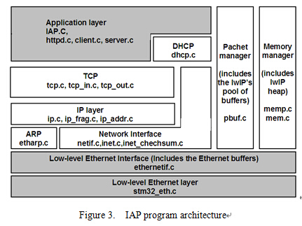
Figure 3. IAP program architecture
IV. MODEL IMPLEMENTATIONģ�͵�ʵ��
The implementation of this IAP method mainly includes two parts of work: the porting of LwIP and the implementation of IAP program.
A. Porting the LwIP to STM32F107
The porting of LwIP stack has 4 steps as showing in the following parts in sequence.
1) Ethernet controller interface
The LwIP comes with a file called ethernetif.c, that works as an interface between the stack and the Ethernet controller. This file is presented as a skeleton to be completed to support a specified architecture.
For the STM32F107, the ethernetif.c (under Utilities\lwip-1.3.1\src\netif) and stm32_eth.c (under Libraries\STM32_ETH_Driver) files constitute the low-level layer, which is the interface between the stack and the Ethernet controller. ethernetif.c contains functions that ensure the transfer of the frames between the low-level driver (stm32_eth.c) and the LwIP stack. Its main function is ethernetif_input, which should be called when a packet is ready to be read from the interface. The low-level layer was set to detect the reception of frames by interrupts. So, when the Ethernet controller receives a valid frame, it generates an interrupt in the handling function, of which the ethernetif_input call is made[4].
2) Periodic LwIP tasks
Apart from setting the Ethernet controller interface, the LwIP has periodic tasks that should be handled. The STM32F107 SysTick is used to build a system clock that serves as the reference to handle the different periodic tasks. The main function of the periodic task handle is LwIP_Periodic_Handle, which is defined in the netconf.c file. This function guarantees the dispatching of the periodic LwIP tasks. The netconf.c file, which is not part of the LwIP stack, ensures the network interface configuration: LwIP initialization, MAC address setting and IP address setting.
3) LwIP configuration
The LwIP can be tuned to suit the application's requirements. The default parameters of the stack can be found in the opt.h file, located under the LwIP directory at src\include\LwIP\. To modify these settings, a new file is defined, lwipopts.h, based on the opt.h file, and located under the LwIP directory at port\. It contains the LwIP configuration for the STM32F107 MCU. Basically these parameters concern:
a) protocol selection, like DHCP, which can be enabled or disabled, defined by LWIP_DHCP
b) the maximum number of simultaneously active connections, for TCP this is defined ��������Ӣ���������ṩ�������ṩ���Ĵ�д��Ӣ�����Ĵ�д����д��������дӢ����������д��ѧ����������дӢ����������ѧ�����Ĵ�д��غ��Ĺؼ���������
3) IAP program architecture
This IAP implementation takes advantage of the STM32F107's Ethernet controller. It consists of a simple HTTP web server on top of the LwIP stack. The ethernetif.c and stm32_eth.c files constitute the low-level layer, which is the interface between the stack and the Ethernet controller. The Ethernet interface layer extracts the data packet from a frame and sends them to the LwIP stack. The LwIP stack handles the packet and forwards the data to the HTTP web server. The IAP program gets data from the HTTP web server, and programs it into flash. Figure 3 shows the IAP program architecture.
The DHCP module of LwIP is an optional module. With this module, the IP address of embedded terminals can be set dynamically, assigned by a DHCP server in the network.
Figure 3. IAP program architecture
IV. MODEL IMPLEMENTATIONģ�͵�ʵ��
The implementation of this IAP method mainly includes two parts of work: the porting of LwIP and the implementation of IAP program.
A. Porting the LwIP to STM32F107
The porting of LwIP stack has 4 steps as showing in the following parts in sequence.
1) Ethernet controller interface
The LwIP comes with a file called ethernetif.c, that works as an interface between the stack and the Ethernet controller. This file is presented as a skeleton to be completed to support a specified architecture.
For the STM32F107, the ethernetif.c (under Utilities\lwip-1.3.1\src\netif) and stm32_eth.c (under Libraries\STM32_ETH_Driver) files constitute the low-level layer, which is the interface between the stack and the Ethernet controller. ethernetif.c contains functions that ensure the transfer of the frames between the low-level driver (stm32_eth.c) and the LwIP stack. Its main function is ethernetif_input, which should be called when a packet is ready to be read from the interface. The low-level layer was set to detect the reception of frames by interrupts. So, when the Ethernet controller receives a valid frame, it generates an interrupt in the handling function, of which the ethernetif_input call is made[4].
2) Periodic LwIP tasks
Apart from setting the Ethernet controller interface, the LwIP has periodic tasks that should be handled. The STM32F107 SysTick is used to build a system clock that serves as the reference to handle the different periodic tasks. The main function of the periodic task handle is LwIP_Periodic_Handle, which is defined in the netconf.c file. This function guarantees the dispatching of the periodic LwIP tasks. The netconf.c file, which is not part of the LwIP stack, ensures the network interface configuration: LwIP initialization, MAC address setting and IP address setting.
3) LwIP configuration
The LwIP can be tuned to suit the application's requirements. The default parameters of the stack can be found in the opt.h file, located under the LwIP directory at src\include\LwIP\. To modify these settings, a new file is defined, lwipopts.h, based on the opt.h file, and located under the LwIP directory at port\. It contains the LwIP configuration for the STM32F107 MCU. Basically these parameters concern:
a) protocol selection, like DHCP, which can be enabled or disabled, defined by LWIP_DHCP
b) the maximum number of simultaneously active connections, for TCP this is defined ��������Ӣ���������ṩ�������ṩ���Ĵ�д��Ӣ�����Ĵ�д����д��������дӢ����������д��ѧ����������дӢ����������ѧ�����Ĵ�д��غ��Ĺؼ���������
 Ӣ��
Ӣ�� �Ĵ�����
 ����
���� ���ô�
���ô� ������
 �¼���
�¼��� ���
��� �ձ�
�ձ� ����
���� ����
���� �¹�
�¹� ������
 ��ʿ
��ʿ ����
���� ����˹
����˹ ������
 ��������
 �Ϸ�
�Ϸ�